Copyright © Shanghai Omega Machinery Co., Ltd. All rights reserved.
How to Size a Single Screw Extruder for Output, Material and Line Requirements
Sep 17,2026
Sizing a single screw extruder is not simply a matter of selecting a larger screw diameter for a higher output target. A practical selection must connect the polymer material, formulation, required throughput, melt quality, screw-and-barrel design, drive capacity, die pressure and downstream equipment into one operating system.
For a new extrusion line, a capacity expansion or a replacement project, the most useful starting point is to define the actual production requirement before comparing machine sizes. The same nominal extruder can perform very differently when processing virgin resin, recycled material, filled compounds, cable insulation, profile formulations or moisture-sensitive polymers. Material condition, screw geometry, temperature control and downstream resistance all affect the stable output that can be achieved in production.
This guide explains the main engineering questions to address when sizing a single extruder. It is intended for technical buyers, process engineers, maintenance teams and project managers who need to evaluate an extrusion system based on process requirements rather than nameplate capacity alone.
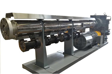
Why Extruder Sizing Is a System Decision
An extrusion line works as a connected process. The extruder must convey and plasticize the material at a rate that the die, filtration equipment, cooling system and downstream handling equipment can accept. If one section of the line is selected without considering the others, the result may be unstable pressure, inconsistent product dimensions, excessive motor load, poor melt quality or output lower than expected.
Why screw diameter alone does not define production capacity
Screw diameter is an important starting point because it influences the volume available for conveying material and is closely related to the possible throughput range. However, it does not provide a complete output prediction. Two extruders with the same screw diameter may produce different results because of differences in effective length, screw profile, compression ratio, channel depth, screw speed, drive torque, barrel temperature control and material behavior.
For example, a line processing a stable virgin polymer pellet may operate differently from a line handling recycled flakes, low-bulk-density film regrind or highly filled compound. The second process may require more attention to feeding consistency, wear protection, filtration, torque reserve and material preparation before its hourly output can be evaluated reliably.
How material behavior changes the sizing decision
The polymer and formulation determine how much energy is required to melt, mix and convey the material. Resin grade, melt flow behavior, bulk density, filler content, moisture level, reinforcement, pigments and additives can all change the loading conditions of the screw and barrel.
A process using abrasive fillers or reinforced compounds may require wear-resistant screw and barrel materials. A moisture-sensitive or heat-sensitive material may need closer control of residence time and barrel temperature. Recycled feedstock may introduce variations in contamination, particle shape, density and melt consistency that are not present in virgin resin processing.
Before selecting the equipment size, the material data should therefore include the polymer family, formulation, source condition, expected variation between batches and the final product requirements.
Why downstream equipment sets practical line limits
The extruder does not operate independently from the rest of the line. Dies, screen changers, melt filters, gear pumps, pelletizers, cooling tanks, haul-off units and winding equipment can all create resistance or impose a maximum usable line speed. A larger extruder will not automatically improve productivity if the downstream system cannot maintain stable pressure, cooling or handling at the increased throughput.
For this reason, an extrusion project should be reviewed from material feeding through to finished-product handling. The target should be stable, repeatable production rather than the highest possible momentary output.
Start with the Production Requirement
The most effective sizing process begins with a documented production brief. This gives equipment suppliers and internal engineering teams a basis for evaluating whether a standard configuration is suitable or whether the screw, barrel, drive system and controls should be adapted for the application.
Define the target product and polymer formulation
Start with the finished product rather than the machine. Identify whether the line will produce pellets, cable coating, profiles, pipes, sheet, film, membrane-related products or another continuous extrudate. The final product affects die design, melt-pressure requirements, cooling method, line speed and dimensional-control needs.
The raw material should be described as precisely as possible. Useful information includes polymer type, grade, melt-flow information if available, additive package, filler percentage, reinforcement type, pigment content, recycled content and moisture condition. If the material is supplied from more than one source, document the expected range of variation rather than providing only the ideal material specification.
Set hourly output, annual volume and operating schedule
The required output should be defined as a stable production target, not only as a maximum theoretical capacity. Consider the planned number of operating hours, shift pattern, expected downtime, product changeovers, scrap allowance and annual production objective.
For example, a process that runs continuously with limited maintenance windows may prioritize drive reserve, component life and process stability. A line that handles smaller batches or frequent product changes may place more value on controllability, cleaning access and practical operating flexibility.
Identify quality requirements for melt temperature and stability
Output is not the only performance measure. The line must also achieve the melt quality required by the final product. Depending on the application, this may include melt-temperature consistency, pressure stability, color uniformity, surface finish, wall thickness, dimensional stability, dispersion quality or pellet appearance.
When the quality requirement is strict, the equipment selection should account for the level of melting, mixing and temperature control needed. Increasing screw speed only to reach a higher throughput can create additional shear heating, pressure changes or residence-time issues if the rest of the process is not designed for that operating point.
How Screw Diameter Affects Output and Process Control
Screw diameter is commonly used as an initial reference when comparing extruder sizes. It influences the available conveying volume and, together with screw speed and screw geometry, affects the throughput range. However, the final selection should be based on the required process window rather than a diameter-only comparison.
Relationship between screw diameter, channel volume and throughput
A larger screw diameter generally provides greater conveying capacity, assuming the screw geometry, rotation speed and material conditions are appropriate. It may be suitable for projects with higher required throughput, larger dies or more demanding downstream processes.
However, throughput depends on more than the physical size of the screw. Actual performance is influenced by material friction, melting behavior, feed consistency, die resistance, screw speed, temperature profile, wear condition and the amount of backflow occurring between the screw flight and barrel surface.
A technical proposal should therefore identify the expected material and operating conditions used to assess capacity. It is more useful to compare output expectations for a defined material and product process than to compare machine size alone.
Why a larger screw is not always the better option
Selecting an oversized extruder can reduce control quality when the intended production rate is much lower than the machine’s efficient operating range. At a low operating level, the process may have less stable feeding, melting or pressure behavior, particularly when the material changes frequently or the downstream equipment requires fine output control.
Oversizing can also increase the initial investment, installed power requirement, space requirement and the amount of material held inside the system during startup, shutdown or grade changes. For heat-sensitive materials, unnecessary residence time may become an additional process concern.
When a smaller extruder provides better control
A smaller extruder may be more appropriate when the required output is moderate, the product has tight dimensional requirements, material changeovers are frequent or the process needs precise low-rate control. It may also be a practical choice for development work, pilot production or specialized applications where process flexibility is more important than high-volume output.
The correct decision is not “larger versus smaller” in isolation. It is whether the selected diameter can operate reliably within the required throughput range while maintaining sufficient torque, melt quality and coordination with the entire production line.
Choosing the Right L/D Ratio
The L/D ratio describes the effective screw length in relation to screw diameter. It is an important design variable because it influences the available processing length for conveying, melting, mixing and pressure development. The most suitable L/D ratio depends on the polymer, formulation, screw design and process target.
How L/D ratio affects melting and residence time
A longer effective processing length can provide additional distance for material melting, mixing and homogenization. This may be useful when the material requires more controlled plasticization or when the process includes demanding pressure and melt-quality requirements.
At the same time, a longer processing path can increase the material residence time and the importance of temperature control. For materials sensitive to thermal history, the design should balance the need for melting and mixing against the risk of overheating or unnecessary degradation.
Material conditions that may require a longer processing length
Applications involving difficult-to-melt formulations, higher filler levels, recycled content, demanding dispersion requirements or certain downstream pressure conditions may require a more carefully designed effective processing length. The answer is not always simply to choose the highest L/D ratio available. Screw profile, compression behavior, channel design, temperature zones and feeding conditions must be considered together.
For example, a process with irregular recycled feedstock may need improvements in material preparation, filtration or feeding before a longer screw alone can provide stable results. Similarly, a filled compound may require wear protection and torque capacity in addition to a suitable L/D ratio.
Balancing homogenization, thermal history and line efficiency
A useful selection question is: what must happen to the material between feeding and the die? The answer may include conveying, melting, mixing, pressure build-up, venting, filtration or stabilization before shaping. Each required function affects the appropriate screw-and-barrel design.
When evaluating L/D ratio, buyers should ask the supplier to explain how the selected configuration supports the material and downstream process. The discussion should include not only the nominal ratio, but also the intended screw geometry, barrel zones, cooling arrangement and operating speed range.
Matching Motor Power, Torque and Screw Speed
The drive system must provide enough power and torque to maintain the required screw speed under normal operating conditions. The correct drive selection depends on the material resistance, screw design, desired throughput, pressure demand and expected variation in the feedstock.
Why torque reserve matters for filled and recycled materials
Filled, reinforced, recycled or variable feedstock can create higher and less predictable resistance during plasticization. A drive system with insufficient torque reserve may experience unstable speed, overload conditions or reduced process control when material properties change.
Torque reserve should be evaluated together with the expected formulation and the intended operating range. It is particularly important to avoid selecting a drive only for ideal laboratory conditions if the production line will process materials with normal commercial variation.
How screw speed affects output and melt consistency
Increasing screw speed can increase throughput, but it may also affect shear heating, pressure behavior, mixing and motor load. The acceptable speed range depends on the material, screw profile, barrel temperature settings and downstream resistance.
A stable line should operate within a practical process window rather than continuously at its highest possible screw speed. The selected motor, gearbox and control system should support the required output without forcing the process to run near its operational limits during normal production.
Questions to ask when upgrading an existing drive system
When an older extruder is being upgraded, collect data from current production before changing the motor or gearbox. Useful records include screw diameter, effective length, screw speed range, motor power, actual motor current, product output, melt pressure, temperature profile, material type and known operating problems.
This information helps distinguish between a true drive-capacity limitation and other causes of low output, such as worn screw-and-barrel components, inconsistent feeding, restricted filtration or excessive die resistance.
Match the Extruder to Downstream Equipment
The extruder should be selected as part of the full extrusion line. Even a well-sized screw and drive system may not produce stable results if the downstream equipment creates excessive resistance, cannot remove heat effectively or cannot handle the intended line speed.
Die pressure and connection requirements
The die determines the final product shape and contributes to the pressure demand placed on the extruder. Connection dimensions, material flow path, die design and required melt pressure should be reviewed before finalizing the extruder configuration.
For replacement projects, provide drawings or dimensions for the existing die connection, adapter, flange arrangement and melt-flow path. This reduces the risk of mechanical mismatch and helps clarify whether additional components are required between the extruder and downstream equipment.
Screen changers, melt filters and pelletizing systems
Screen packs, melt filters and screen changers can improve melt cleanliness, especially when processing recycled materials or compounds with contamination risk. They also create pressure resistance that must be considered during extruder and drive selection.
Pelletizing systems, including strand pelletizing, water-ring pelletizing or other downstream arrangements, should be matched to melt temperature, pressure stability and throughput. If the project includes a screen changer, melt pump or filtration system, provide its expected operating conditions during technical evaluation.
Cooling, haul-off and line-speed coordination
For pipe, profile, sheet, film and cable applications, cooling and haul-off capacity are essential to practical output. The line must cool and handle the extrudate at a rate that matches the melt delivery from the extruder. A mismatch can cause dimensional variation, distortion, surface defects or unstable line operation.
Review the complete sequence from die exit to final collection or winding. This includes cooling length, water temperature where applicable, vacuum calibration, haul-off capacity, cutting or winding speed, and the available production space.
For projects that require equipment selection by material, output and downstream configuration, review the available single screw extrusion solutions for polymer processing before confirming a final machine arrangement.
Selection Checklist for a New or Replacement Extruder
A structured technical brief improves the accuracy of equipment selection and reduces avoidable revisions during quotation, design and commissioning. The following checklist can be used when preparing a new project or evaluating a replacement extruder.
| Selection Item | Why It Matters | Information to Prepare |
|---|---|---|
| Polymer and formulation | Determines melting behavior, torque demand, temperature control and wear conditions. | Resin type, grade, fillers, additives, recycled content and moisture condition. |
| Finished product | Defines die requirements, melt quality needs, cooling method and downstream equipment. | Product drawing, dimensions, application and quality requirements. |
| Target output | Provides the basis for selecting screw diameter, speed range, drive capacity and line speed. | Required kg/h, operating schedule, annual volume and acceptable output variation. |
| Screw and barrel design | Influences conveying, melting, mixing, pressure development and component service conditions. | Existing screw drawing, diameter, L/D ratio, original model and known production issues. |
| Drive system | Must maintain stable operation under normal material and pressure conditions. | Motor power, gearbox data, speed range, motor current and available electrical supply. |
| Downstream equipment | Sets practical pressure, cooling, handling and speed limits for the line. | Die details, screen changer, filtration equipment, cooling system, haul-off and pelletizing information. |
| Wear and corrosion conditions | Influences screw and barrel material selection and maintenance planning. | Filler type, reinforcement, contaminants, corrosive additives and current wear observations. |
Information to collect before requesting a technical proposal
- Polymer type, resin grade, formulation and recycled-material percentage.
- Material form, including pellets, powder, flakes, film regrind or compounded material.
- Target product type, product drawing and key dimensional requirements.
- Required stable output in kg/h and planned operating hours.
- Existing extruder model, screw diameter, L/D ratio, motor power and screw-speed range, if applicable.
- Die, adapter, screen changer, filtration system and downstream equipment details.
- Known process issues, such as low output, pressure fluctuation, material degradation or excessive wear.
- Required documentation, inspection records, trial requirements and project acceptance criteria.
Common sizing mistakes that increase commissioning risk
One common mistake is selecting an extruder only from a maximum output figure without defining the resin, formulation and downstream process used to reach that result. Another is treating screw diameter as the only sizing variable while overlooking L/D ratio, screw profile, torque reserve, temperature control and die resistance.
Projects can also encounter problems when the existing downstream line is not reviewed before an extruder upgrade. A larger machine may increase melt delivery, but the die, filter, cooling system or haul-off unit may become the next production limitation.
For processes with unstable output, pressure variation or repeated overload conditions, it is useful to first identify whether the cause is material preparation, feeding, process settings, downstream resistance or screw-and-barrel wear. See this guide to diagnosing unstable extruder output and pressure when evaluating an existing line before selecting replacement equipment.
Extruder Sizing Flow for Technical Evaluation
The following sequence can be used as a practical framework for new equipment, replacement machines and extrusion-line upgrades.
- Define the finished product, polymer formulation and target quality requirements.
- Confirm the required stable output, operating schedule and expected material variation.
- Assess the feedstock condition, including moisture, bulk density, filler level and contamination risk.
- Select the preliminary screw diameter and operating speed range based on the required process window.
- Evaluate L/D ratio, screw geometry, barrel zones and cooling requirements for melting and homogenization.
- Confirm motor power, gearbox capacity and torque reserve for normal and variable production conditions.
- Match the extruder outlet, pressure capability and controls with the die, filtration equipment and downstream line.
- Review screw-and-barrel materials for abrasion, corrosion and expected service conditions.
- Agree on drawings, inspection requirements, trial conditions and acceptance criteria before production.
For projects involving abrasive fillers, reinforcement, recycled content or corrosion-sensitive compounds, screw-and-barrel material selection should be evaluated alongside equipment sizing. Omega’s wear-resistant single screws for extrusion equipment include custom design options based on material type, finished product, target yield, motor power, maximum screw speed and original screw data. The available material options include nitriding steels, vacuum-hardened steels and alloy-layer solutions for different operating conditions.[23]
FAQ: Single Screw Extruder Sizing
How do I estimate the screw diameter needed for my target output?
Begin with the polymer type, formulation, target stable output, final product and downstream process. Screw diameter is related to throughput potential, but the final selection also depends on screw profile, L/D ratio, speed range, drive torque, die resistance and material condition. A supplier should evaluate these factors together rather than recommending a diameter from output alone.
Does a longer L/D ratio always improve extrusion quality?
No. A longer L/D ratio can provide additional processing length for melting and homogenization, but it can also increase residence time and temperature-control requirements. The appropriate ratio depends on the material, required mixing, thermal sensitivity, screw design and downstream process.
What data should be provided for a replacement extruder project?
Provide the existing screw diameter, effective length, L/D ratio, motor power, screw-speed range, output record, material information, die connection dimensions, downstream equipment details and known production problems. Original drawings and component measurements are useful when replacement screws or barrels are also required.
Can one extruder process different polymer grades?
In many cases, one machine can process more than one grade within a compatible polymer family. However, the practical range depends on differences in melt behavior, filler content, moisture sensitivity, processing temperature and required output. Significant material changes may require adjustments to the screw profile, temperature settings, filtration or feeding arrangement.
Should a recycled-material line be sized differently from a virgin-resin line?
Usually, yes. Recycled feedstock can vary in bulk density, particle shape, moisture, contamination level and melt behavior. The extrusion system may need additional attention to feeding, drying, filtration, torque reserve, wear protection and process monitoring. Learn more about design considerations for recycled plastic extrusion when planning a line for recycled materials.
Use Process Data to Make a Practical Selection
A reliable extrusion system is selected from the required process conditions, not from a single capacity figure. The most useful technical discussion starts with the material, finished product, target stable output and downstream line arrangement. From there, screw diameter, L/D ratio, drive power, temperature zones, screw-and-barrel materials and connection requirements can be evaluated as a complete system.
For equipment projects involving polymer processing, cable production, recycled plastics, profiles, pipes, sheet, film or specialty applications, the available custom single screw extrusion equipment can be reviewed according to the material and production-line requirements. The technical information prepared for an inquiry should include the target process, material details, output requirement, relevant drawings, downstream equipment interfaces and any requirements for testing or inspection documentation.
Next News- Information
- What are the reasons for the unstable dimensions of the profiles during the extrusion process? What are the solutions?
- What is the forming process of plastic-steel profiles? What are the key issues during forming compared to conventional profiles?
- What are the causes of the brittleness of extruded PVC profiles? And what are the solutions?
- What are the strategies to improve dimensional and geometric accuracy in profile production?
- How should a worn barrel be repaired?
- How should the counter-rotating twin-screw extruder be operated during no-load testing?
- How can internal stress concentration in profile cross-section design be minimized as much as possible?
- How can internal stress concentration in profile cross-section design be minimized as much as possible?
- What are the requirements for molding equipment and process control when producing APET sheet?
- How to enhance the low-temperature impact resistance and aging resistance of PP pipe materials?
- Contact Us

-
Shanghai Omega Machinery Co., Ltd.
Add.: No.168 Hualian Road, Putuo District, Shanghai City
Contact: Nina
Tel.: +86-021-69921527
Mobile: +86-15021464410
Fax: +86-021-69921567
E-mail: omegajessica@163.com;965425705@qq.com
WeChat No.: 1131449532
Whatsapp: +86 159 0054 6558

-